PRS SE Standard 24 Wiring
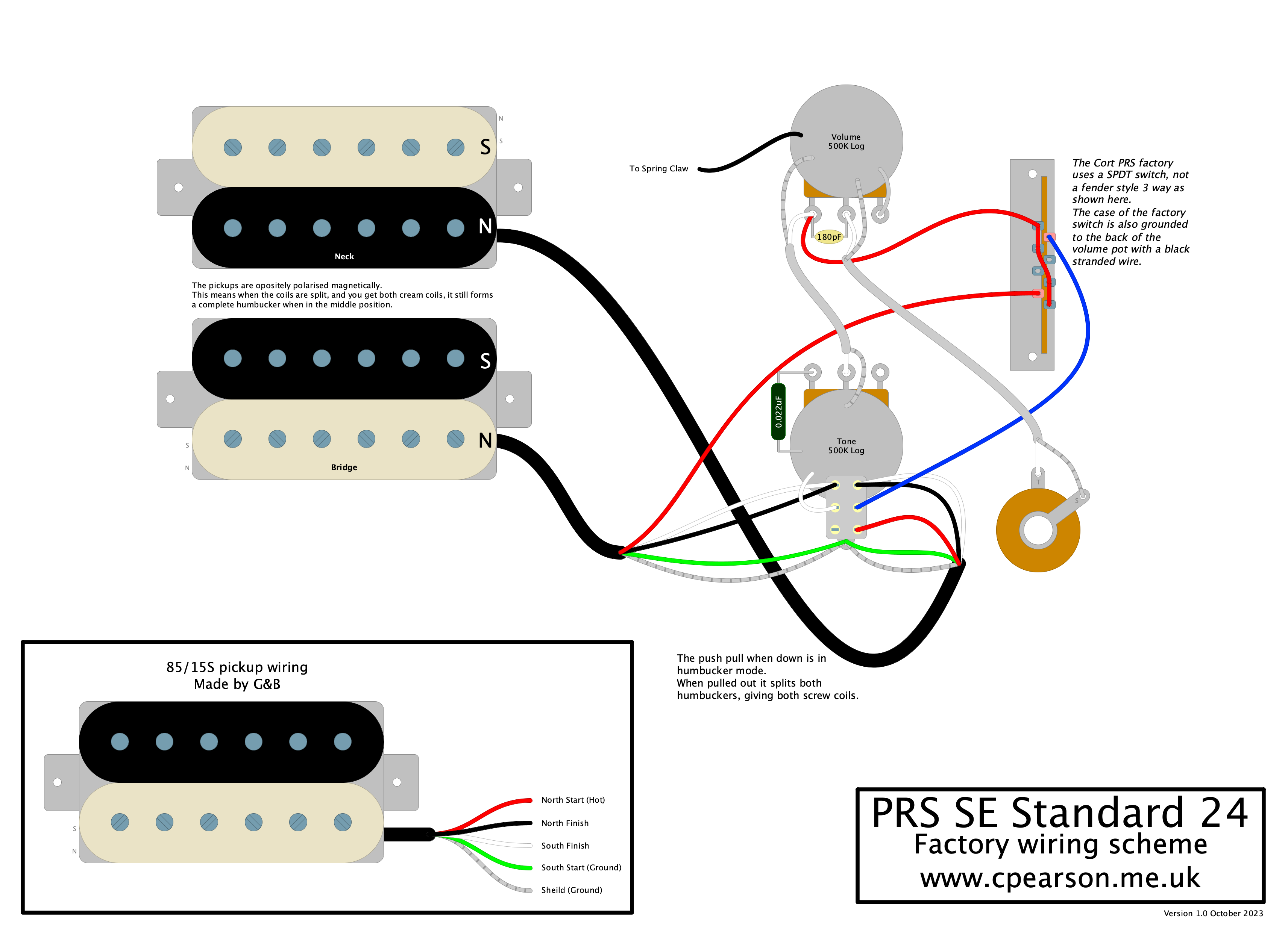
I was curious what the seemingly overly complex bundle of wire was doing in my PRS SE Standard 24. I knew it was coil tapping but more was going on than the normal diagrams I’d seen. With the help of DIY Layout Creator I drew out the wiring to figure it out.
I also had to work out what the colour codes are used on the G&B manufactured 85/15S pickups. After looking at how the pickups were wired up it seems they shared the same colors as DiMarzio pickups, but there is a chance I have the black and white flipped.
click image to embiggen
As a summary, the wiring is “modern” using typical values for the pots and tone capacitor. There is a capacitor only treble bleed.
The push pull tone pot works to split the coils. When the knob is down then you get both humbuckers.
When the knob is pulled up, it grounds out one of the coils on each humbucker, removing it from the circuit. What is clever is you are left with one of each polarity so in the middle position you retain the hum cancelling.
The bridge pickup is the standard layout where the 2nd coil in the path is grounded, leaving the North polarised screw coil.
On the neck pickup the wiring is a little different, and it cuts the first coil out of the circuit and swaps to use the middle link as the new “hot” connection. This means you’re using the South polarised screw coil.
The two pickups are magnetically opposite, so even though you split to two of the screw coils, you have a north coil and a south coil, effectively both sides of a humbucker, just wired in parallel not series. This means that the hum cancels the same as it would in a typical humbucker.